A list of Australian Standard Specificatiociationd Codes is availableen l état PREFACE
This edition of the SAA Code for Concrete in Buildings has been prepared by. Committee BD/2,
*Concrete Structures, as a revision of the 1958 edition.
It incorporates many amendments to the text of the former edition arising eithee fom experiencies the Adolitat nas fist bedition er because of chanigg
structures.
Account has also been taken of the revision of
the American
Concrete Institute's Building Code Requirements for Rein
forced Concrete.
A separate design code has been developed to cover the use of prestressed concrete in building and has been issued as AS
CA35.
Because of incomplete work in relation to fire resistance requirements generally, Appendix B dealing with these requirements has been temporarily withdrawn from this edition, but rule references to the appendix have been retained in anticipation of the early completion of the fire resistance require. ments, which will then be added to this edition by amendment*
The
former Appendix E, Notes on the Evaluation of Compressive Strength Tests of Concrete, has been deleted with the intention of covering this matter more fully in a separate document.
A further section, to cover composite con-
struction, is nearing completion and will be added by way of an amendment, when accepted by the committee†.
The resistance to pull-out of twisted square bars has received close
Chart to determine appropriate values.
lesteforced
A separate design code has
Decis
stressed concrete in building and has been issued as
Because of incomplete work in relation to fir resistance fequirements generally, Appendix B dealing with these requirements has been tomporarity withdrawn from this edition, but rule references to the appendix have been retained in anticipation of the early completion of the fire resistance require-
ments, which will then be added to this edition by amendment"
Appendix E, Notes on the Evaluation of Compressive Strength Tests of Concrete, has been deleted with the intention of covering this matter more fully in a separate document.
A further section, to cover composite con-
struction, is nearing completion and will be added by way of an amendment, when accepted by the committeet.
The resistance to pull-out of twisted square bars has received close
concrete to the bar and subsequently, as the load increases, to the mechanical resistance due to the shape of the bar.
The factor of 1:5 for twisted square
bars (R factor, Table 5) has been based on the average value of the pull-out resistances for free-end slips of 0-002, 0-005, 0-01, 0-02 and 0-04 in.
This
method of computing the factor takes into account the shape of the curve for load-resistance/slip, and the value determined more truly represents the behaviour of the bar than would taking the load-resistance corresponding to an arbitrary single free-end slip, say of 0•01 in.
It is also important to
note that the factor 1.5 only applies to bars having a maximum pitch of twist of 12D and an untwisted length on ends not exceeding 4D.
AS A83
is to be amended in accordance with these altered requirements.
the onnortunitv has been taken to number the rules
radeoconcrete to the bar and subsequently, as the load
resistance due to the shape of the bar. The factor of 1-5 for twisted square resistance due to the shape of the bar.
The factor of 1•5 for twisted square
bars (k factor, Table 5) has been based on the average value of the pull-out resistances for free-end slips of 0-002, 0-005, 0-01, 0:02 and 0-04 in. method of computing the factor takes into account the shape of the curve for load-resistance/slip, and the value determined more truly represents the behaviour of the bar than would taking the load-resistance corresponding to an arbitrary single free-end slip, say of 0-01 in. It is also important to note that the factor 1.5 only applies to bars having a maximum pitch of twist of 12D and an untwisted length on ends not exceeding 4D.
AS A83
is to be amended in accordance with these altered requirements.
During the revision, the opportunity has been taken to number the rules according to the practice now in general use for other major SAA codes,
*Issued as Amendment No. 1 and incorporated in the 1965 reprint.
+Issued as Amendment No. 3 and incorporated in the 1965 reprint. 3. Construction Tolerances
4. Maximum Values of ID Ratio of Beams and Slabs
5. Permissible Stresses in Normal Reinforced Concrete
6. Permissible Stresses in Steel Reinforcement
22
25
30
32
33
7. Permissible Axial Loads on Centrally Loaded Compression Members
8. Bending Moment Co-efficients
-Slabs
Spanning in Two Directions
38
at Right Angles Simply Supported on Four Sides
9. Bending Moment Co-efficients- Rectangular Slabs Supported on
41
Four Sides with Provision for Torsion at Corners
10. Stress Reduction
Co-efficients for
Slender Beams
Subject to
43
Transverse Loads Only
11. Stress
Reduction
Co-efficients for Slender
Beams Subject to
43
Combined Transverse and Axial Loadings.
12. Minimum
Centre-to-centre Spacing of Longitudinal
Steel in
57
Compression Members
13. Minimum Splice Lap for Plain Longitudinal Bars in Compression
57
Members...
14. Distribution between Column Strips and Middle Strips in per cent of Total Moments at Critical Sections of a Panel
15. Moments in Flat Slabs in Percentages of Mo
16. Minimum Length of Negative Reinforcement
17. Minimum Length of Positive Reinforcement
18. Percentage Increase in Permissible Loads on Walls
19. Ultimate Load on Shear Connectors
Al. Assumed Depth of Neutral Axis in T Beams
BI. Assessed Fire-resistance Ratings for Columns10. Stress
Reduction
Co-efficients
for
Slender
Subject
Transverse Loads Only
43
11. Stress
Reduction
Co-efficients
Stress Reduction So endiesial Loadings...
Slender Beams
Subject to
43
12. Minimum
Centre-to-centre Spacing of Longitudinal Steel in
57
Compression Members
13. Minimum
Splice Lap for Plain Longitudinal Bars in Compression
57
Members..
14. Distribution between Column Strips and Middle Strips in per cent of Total Moments at Critical Sections of a Panel
68
15. Moments in Flat Slabs in Percentages of Mo
72
16. Minimum Length of Negative Reinforcement
76
17. Minimum Length of Positive Reinforcement
77
18. Percentage Increase in Permissible Loads on Walls
84
19. Ultimate Load on Shear Connectors
.. 102
Al. Assumed Depth of Neutral Axis in T Beams
... 106
BI. Assessed Fire-resistance Ratings for Columns
... 113
B2. Assessed Fire-resistance Ratings for Reinforced
... 114
Construction
B3. Typical Fire-resistance Requirements
..•
... 118
D1. Proving Test Requirements for Steel Reinforcing Bars and Wire 124Page
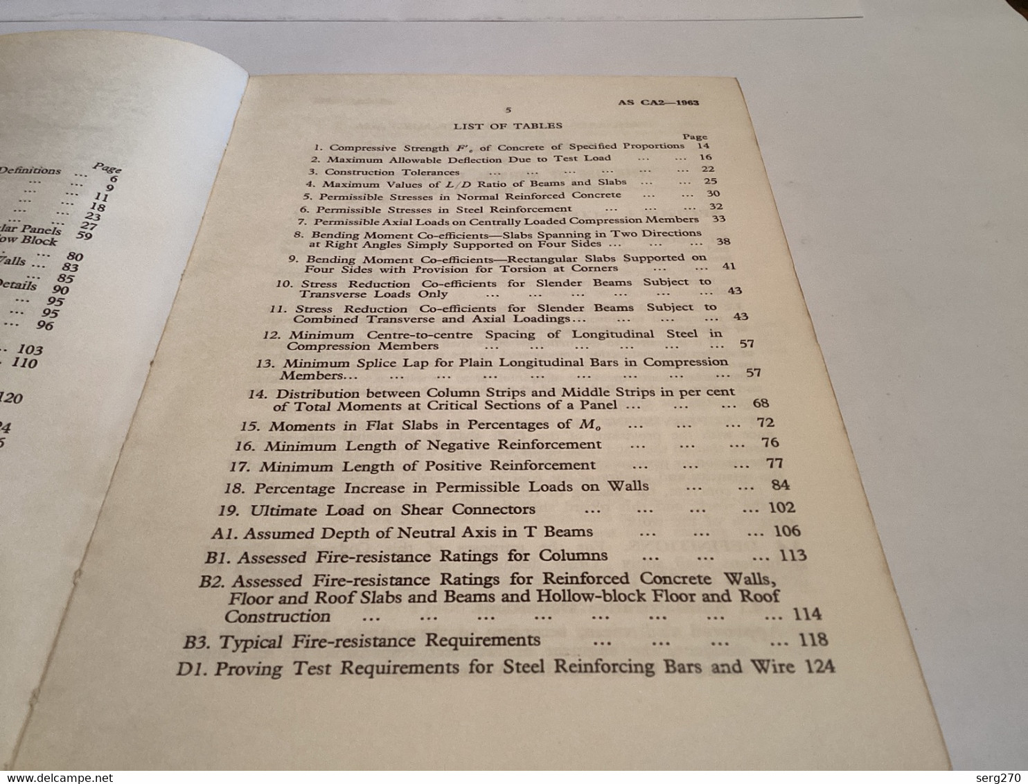
1. Compressive Strength F'. of Concrete of Specified Proportions
14
2. Maximum Allowable Deflection Due to Test Load
16
3. Construction Tolerances
22
4. Maximum Values of L/D Ratio of Beams and Slabs
25
5. Permissible Stresses in Normal Reinforced Concrete
30
6. Permissible Stresses in Steel Reinforcement
...
32
7. Permissible Axial Loads on Centrally Loaded Compression Members 33
8. Bending Moment Co-efficients-Slabs Spanning in Two Directions at Right Angles Simply Supported on Four Sides
• . .
38
9. Bending Moment Co-efficients- Rectangular Slabs Supported on
Four Sides with Provision for Torsion at Corners
41
10. Stress Reduction Co-efficients for Slender Beams Subject to
Transverse Loads Only
..
43
Straco
Paderation
AMARACONTENTS
Scope, Extent and Application, and Definitions Materials
Concrete Proportioning and Testing
Construction
Bases of Design
Design Based on Permissible Stresses
Design of Flat Slabs with Square or Rectangular Panels
Besien of Floors and Roofs of Ribbed and follow Block Construction
Design of Load Bearing Reinforced Concrete Walls
...
Footings
Reinforcement, Pipes and
Conduits-
•General Details
Precast Concrete Building Units
Earth Retaining Structures
Composite Construction ...CONTENTS
1.
Scope, Extent and Application,
and Definitions
Materials
Concrete Proportioning and Testing
Construction
Bases of Design
Design Based on Permissible Stresses
Besign of Flat Slabs with Square Rectangular Pancis
Besign of Floors and Roofs of Ribbed and Hollow Block
Construction
Design of Load Bearing Reinforced Concrete
Walls
Footings
Reinforcement, Pipes and
Conduits- General Details
298 44865008
Precast
Concrete
Building Units
90
95
Earth Retaining
Structures
Composite Construction
95
96
Design Based on Ultimate Strength
Requirements for Fire Resistance
•• 103
• 110
Standard Method of Test for the Comparison of Bond
Resistance
reststand roving Test for Steci Reinförcing Bars and
Field Methods of Test for Aggregate
• 124
. 126
*• 131


 Discover the collectors' agenda!
Discover the agenda
Discover the collectors' agenda!
Discover the agenda